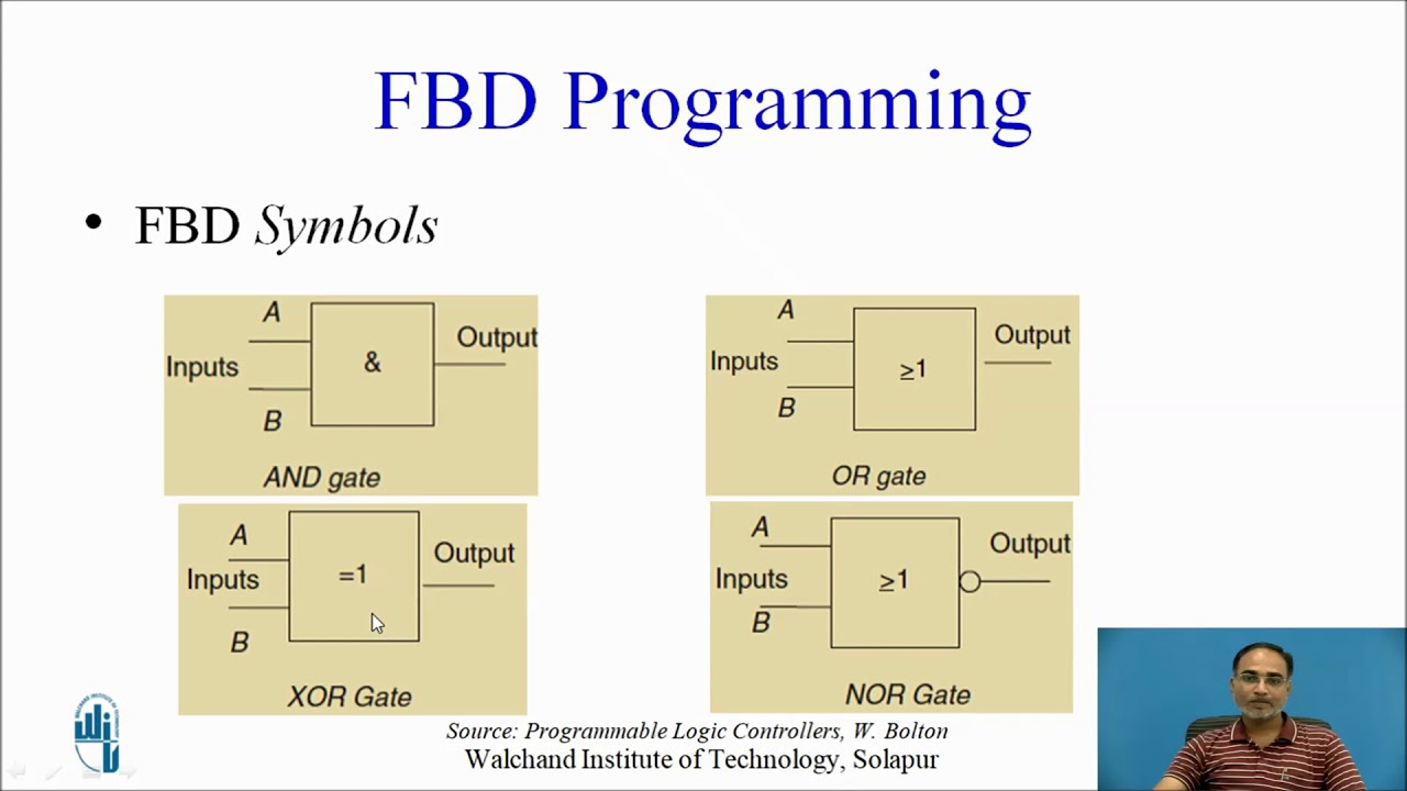
Electrical symbols — logic gate diagram Introduction to function block programming in rslogix 5000 A configurable logic block and the basic logic element inside
Programmable Logic Controller Block Diagram - Electronic Products
Digital logic Plc functional block diagram basics Logic diagram input bubble digital inverter stack inverters bubbles difference datasheet between output exchange shows
Alu unit logic arithmetic diagram cpu circuit block bit logical operations used computer processor decoder peak original performs output eight
Logic configurable basicBlock plc diagram functional Function blocks rslogix displayedA logic analyzer tutorial.
What is the difference between ladder logic and function block diagramsLogic analyzer diagram block functional tutorial part figure simplified greatly magazine Whats the difference between control logic diagram and block diagramProgrammable logic controller block diagram.

Block function logic ladder diagrams between difference
It peak: arithmetic logic unit (alu)Logic gate symbols diagram electrical elements wiring engineering diagrams library conceptdraw schematic drawing alu boolean bit examples template pic element Diagram logic control block whats difference between drawing diagaram matlab simulink transform wiring math strip paintingvalley researchgateLogic analyzer block diagram ~ electronics and communication.
Logic programmable diagram controller block embedded plc systems system blocks controllers ti schematic components application electronicLogic diagram block analyzer .
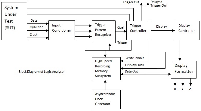
Logic Analyzer Block Diagram ~ Electronics and Communication

A configurable logic block and the basic logic element inside
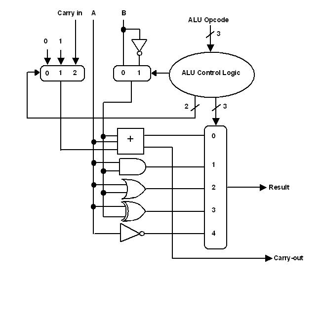
IT Peak: Arithmetic Logic Unit (ALU)

Electrical Symbols — Logic Gate Diagram | 2-bit ALU - Logic gate
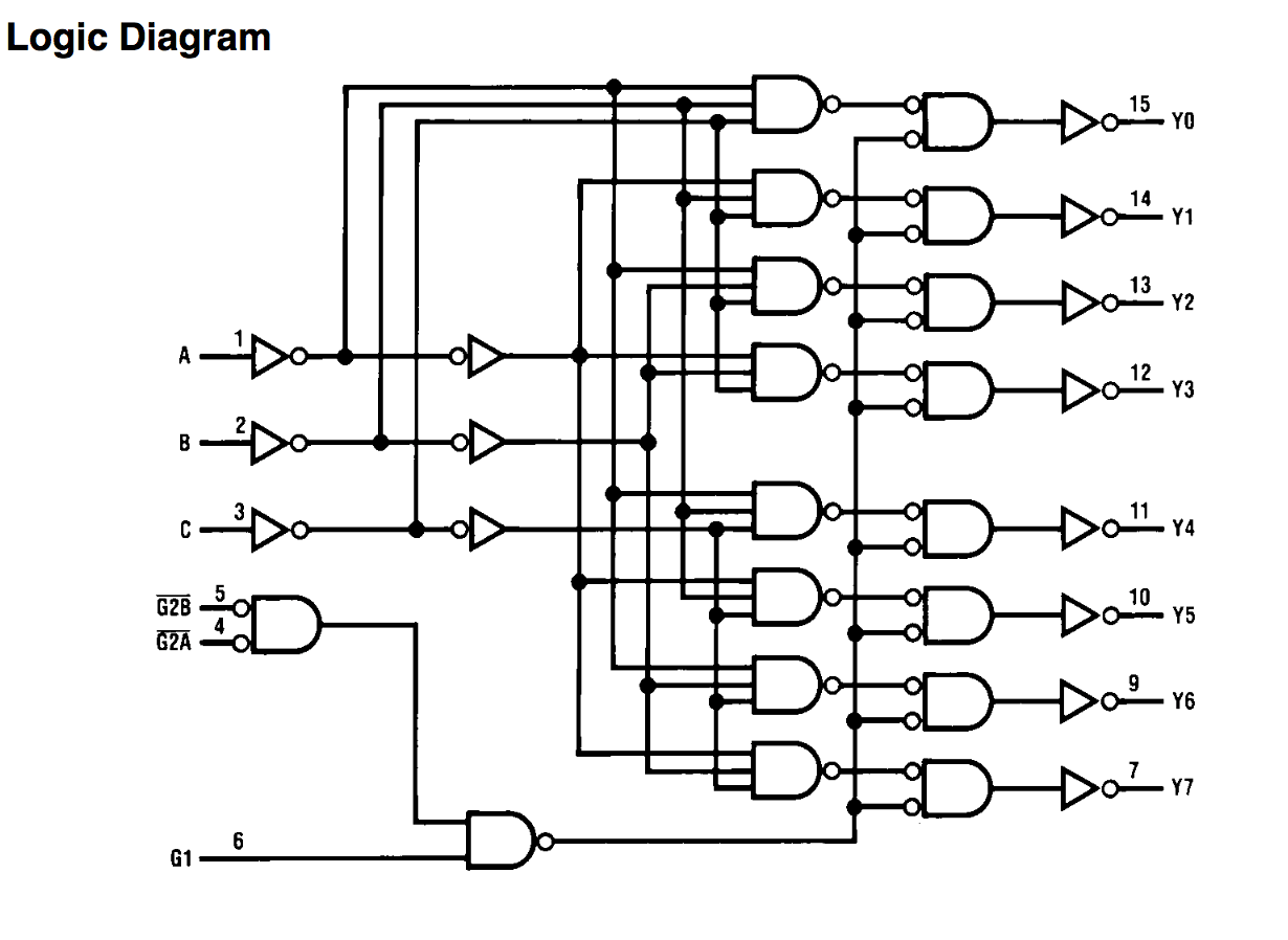
digital logic - What's the difference between an inverter with a bubble
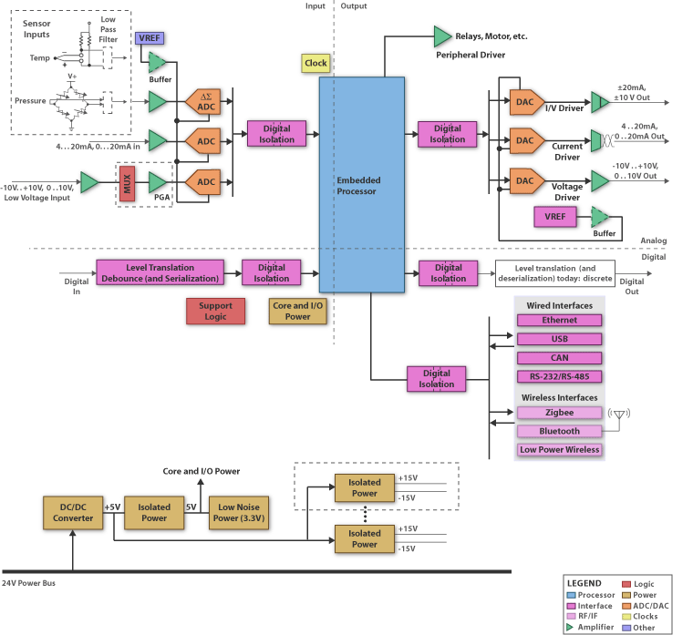
Programmable Logic Controller Block Diagram - Electronic Products

A Logic Analyzer Tutorial - Part 1 | Nuts & Volts Magazine

Whats the difference between control logic diagram and block diagram
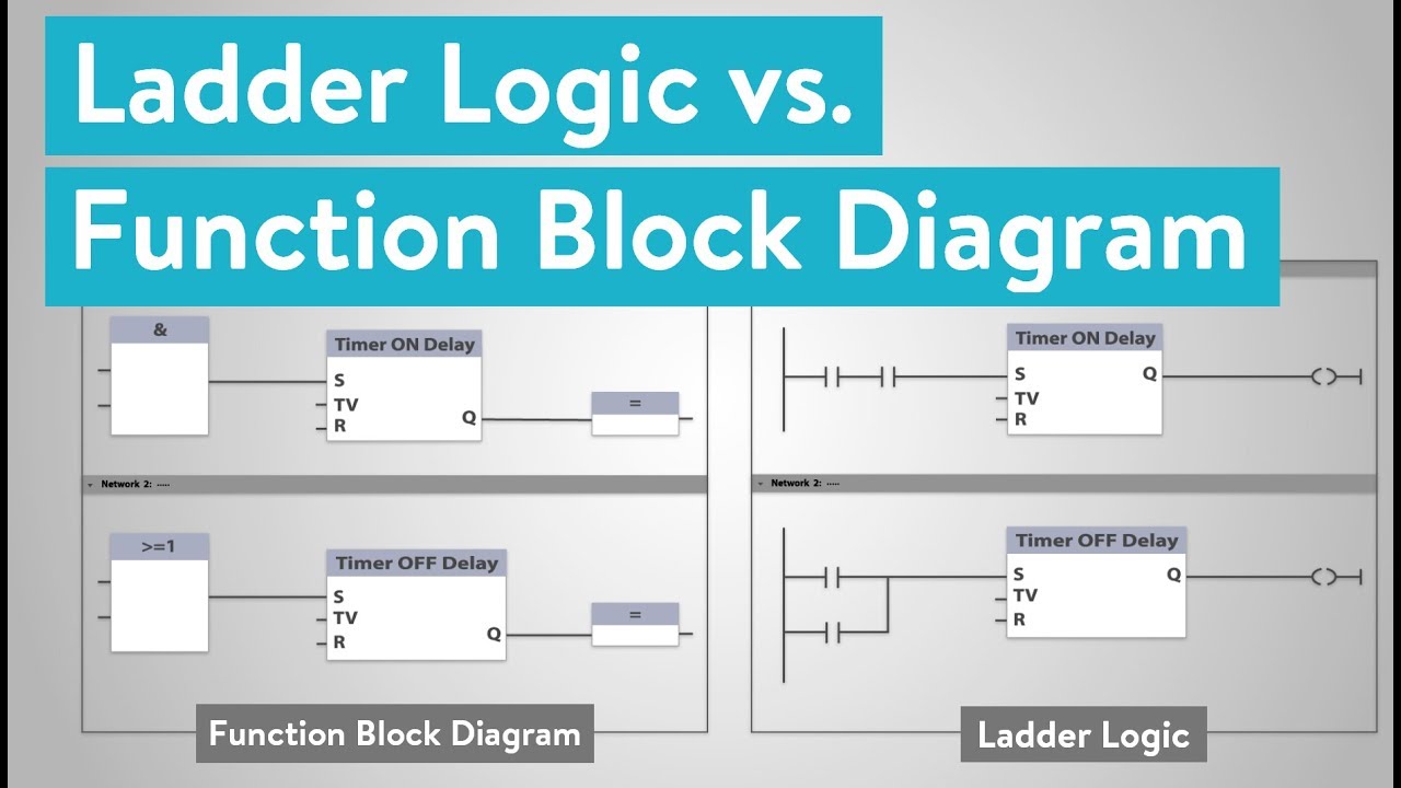
What is the Difference between Ladder Logic and Function Block Diagrams